Geotechnics for Hazard Mitigation
Rapid development of urban areas originated from plains and lowlands towards hills in the suburbs poses increasing risks in geo-hazards. The potential geo-hazards include soil liquefaction during earthquakes, collapse of artificial cut-and-fill, and slope instability. A series of strategic measures are required for mitigating these geo-hazards and establishing higher performance of geotechnical works.
Various approaches are adopted for achieving these objectives, such as nonlinear effective stress analysis of soil-structure systems constructed on saturated sandy deposits, global modeling of geo-hazards based on the use of GIS and urban geo-data base, experimental studies through geotechnical centrifuge.
Academic Staff
Ryosuke UZUOKA
 Professor (Disaster Prevention Research Institute)
Research Topics
Study on combined disaster induced by rainfall, earthquake and tsunami etc. To understand the ground and structure behaviour under different external forces with time difference such as earthquake after rainfall, rainfall or tsunami after earthquake. To develop dynamic numerical analysis of various structures on saturated/unsaturated ground based on porous media theory with finite deformation. To improve reliability of numerical simulation based on uncertainty quantification (UQ) with Verification & Validation (V&V) method.
Contacts
Room E-415D, Disaster Prevention Research Institute, Uji Campus
TEL: +81-774-38-4090
FAX: +81-774-38-4094
E-mail: uzuoka.ryosuke.6z kyoto-u.ac.jp
Kyohei UEDA
Associate Professor (Disaster Prevention Research Institute)
Research Topics
Main subjects of my research activities are to study the dynamic deformation mechanism of soil-structure systems due to the strong nonlinearity of ground (e.g. liquefaction) and to improve the prediction accuracy of the damage to soil-structure systems during large earthquakes. I have been engaged in the improvement of a constitutive model for granular materials such as sands based on the finite strain theory and the development of a ground response analytical method incorporating the model. By successfully coupling experimental approaches (e.g. centrifuge model tests, laboratory soil tests) and theoretical/analytical approaches, I would like to proceed with research for the damage mitigation of soil-structure systems during earthquakes with exploring the essence of dynamic events.
Contacts
Room E-414D, Disaster Prevention Research Institute, Uji Campus
TEL: +81-774-38-4092
FAX: +81-774-38-4094
E-mail: ueda.kyohei.2v kyoto-u.ac.jp
Research Topics
Damage estimation of soil-structure systems during large earthquakes
More than 6000 people were killed and destructive damage on infrastructures, such as lifelines, bridges, and port facilities, were trrigered by the 1995 Hyogoken-Nanbu, Japan, Earthquake. Among these damaged infrastructures, soil- structure systems, such as wharves and/or bank protection around reclaimed land and river dykes, suffered catastrophic damage mainly due to soil liquefaction. The damage was also severe in terms of restoration period and its cost. Therefore it became socially imperative to estimate the degree of damage on these structures after earthquakes with higher accuracy.
To analyze and estimate the damage, the computer program called FLIP has been developed. The FLIP is an FEM program for the effective stress analysis with multiple shear mechanism of sands. It has been used to analyze and estimate the degree of damage on various infrastructures. As examples, Figure 1 and 2 show a result of the analysis for the Kobe Bridge, which suffered severe damage during the Hyogoken-Nanbu Earthquake, and a simulation result of the behavior of a gravity type quay wall in centrifuge model tests, respectively (red color indicates high excess pore water pressure in both figures).

Figure 1: Analysis of the Kobe Bridge during the Hyogoken-nanbu Earthquake
Figure 2: Liquefaction analysis (3D) of gravity type quay wall during earthquakes
Improvement of a constitutive model of soils based on the concept of multiple shear mechanism
In order to precisely predict the damage of soil-structure systems during earthquakes, it is necessary to appropriately represent the dynamic behavior of geotechnical materials from small strain range to non-linear region including liquefaction in numerical simulation. Our laboratory has proposed a constitutive model of soils (called Cocktail Glass Model) as a mechanical model for granular materials such as sands based on the concept of multiple shear mechanism. This model originates from interpreting soils as granular materials, which are composed of masses of soil particles, and is capable of expressing the changes in the internal structure due to the contact force between the particles.
By plotting the dilative component of dilatancy and the virtual simple shear strain on the vertical and horizontal axes, respectively, in the Cocktail Glass Model, a flower of butterfly shape shown in Figure 3 appears as the structure of stress-induced anisotropy for an assembly of soil grains. This model, which has been incorporated into the above-mentioned numerical analysis program (FLIP), can take into account the effect of dilatancy characteristic of granular materials and its related induced anisotropy appropriately.
Figure 3: Evolution of strain space fabric during macroscopic biaxial shear
Improvement of a constitutive model based on the finite strain theory and development of ground response analytical method
Soils show a significant nonlinearity when subjected to large ground motions and finally lead to liquefaction with the loss of its strength. In order to predict the dynamic behavior of soil-structure systems due to liquefaction with a high degree of accuracy by numerical simulation, the soil behavior has to be accurately modeled including at large deformation region.
Towards the improvement of numerical simulation, our laboratory has extended the above-mentioned strain space multiple shear mechanism model based on the finite strain theory and developed a large deformation analysis program (called FLIP/TULIP) for soil-structure systems incorporating the extended model. In the program, both the Total Lagrangian (TL) and Updated Lagrangian (UL) formulations are available. Results of seismic response analyses for an embankment shown in Figure 4 indicate the numerical equivalence of the TL and UL formulations and the validity against the dynamic behavior of embankments on liquefiable deposits.
Figure 4: Large deformation analyses for an embankment during an earthquake
Centrifuge experiments on the seismic behavior of group pile foundations
Pile foundations in saturated sand deposit are quite often encountered for structures constructed on reclaimed lands and/or port facilities. After the 1995 Hyogoken-Nanbu, Japan, Earthquake, failures of pile foundations in saturated sand deposit have been reported and regained an increasing attention for subjects of design and research.
The possible causes of these failures might be the lateral force by the lateral movement of soils due to liquefaction, and/or inertia force of super-structures and soils around foundation during shaking. Failure of pile foundations severely affects the usability of structures, therefore it is important to understand the failure mechanism of pile foundations in liquefied ground to improve their performance against seismic forces.
We have investigated the causes of these failures using the geotechnical centrifuge (Figure 3) and observed the interaction between structures and surrounding soils.

Figure 5: Geotechnical centrifuge at DPRI (Radius=2.5m)
Study on the deformation mechanism of soil-structure systems due to long-duration earthquakes and tsunami
During the 2011 off the Pacific coast of Tohoku Earthquake, a structure made of reinforced concrete having a pile foundation collapsed due to tsunami. In this case, the liquefaction of ground has been considered to accentuate the damage in combination with the tsunami wave force. In the case of a baymouth breakwater, the possibility of a complex disaster caused by earthquake and tsunami - the failure of the breakwater due to the effect of seepage flow through the rubble mound due to water head difference due to tsunami in combination with the wave force action - has been pointed out.
Thus, our laboratory performed a series of centrifuge model test for a caisson-type quay wall on rubble mound by using a special container for simulating tsunami in centrifugal field in order to clarify the complex failure mechanism of breakwaters due to tsunami (Figure 6). The results have demonstrated the importance of the mechanism of failure in the rubble mound due to seepage flow of pore water in addition to the wave force of tsunami action. In particular, the results without the seepage flow by artificially covering the side of the oncoming wave using rubber membrane have revealed that there might have been no damage or only slight damage to the breakwater without the effect of seepage flow in the rubble mound.
Figure 6: Results of centrifuge model tests for breakwater with tsunami
Verification of generalized scaling law for centrifuge model tests
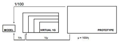
When performing a centrifuge experiment by using a scaled-down small size model, the scaling law for a centrifugal field should be applied in order to reproduce the in-situ stress-strain relationship of soils in the model scale. The conventional scaling law makes it possible to carry out an experiment with the reduced size model, but there is a limit to the prototype scale that can be reproduced in a centrifugal field because the reduced scale ratio has the upper limit due to the performance of centrifuge machines.
In order to resolve the restriction and satisfy demands for the testing of large prototypes, our laboratory has proposed a new scaling law (called generalized scaling law) by setting a virtual 1G field between a prototype and a centrifugal field (Figure 7). In addition, we are studying about the applicability of the generalized scaling law to various ground conditions (e.g. dry or saturated, lateral or inclined) with and without structures (e.g. pile foundation) by performing a series of centrifuge model tests.

Figure 7: Concept of the generalized scaling law
